
Rotating, scaling and moving in three dimensions

I've come across some interesting articles on how to do 3D on the net, but in my opinion, none were really explained in the most intuitive way. The purpose of this article is to try and explain exactly what's happening, step by step, so that you can not only create a successful 3D routine, but also understand it - so that you can manipulate and adapt the code into something more.
Also, you'll discover that the math and logic behind 3D is not as blindingly complex as might first appear. I've done my utmost to keep the code as short and efficient as possible, whilst also making it as easy to follow as possible. As I mentioned earlier, the code I'll use will be closer to something BASIC-ish rather than outright C or machine code. This is so that (hopefully) everyone will be able to understand. Also, you'll need to use floating point arithmetic, because the decimal point is needed.
What the program will do: In a nutshell, when it's finished, the program will convert a batch of 3D coordinates into '3D-erized' 2D coordinates, so that they can be displayed on the screen.
What stuff you'll obviously need to start with:
Numerous object coordinates (X, Y, Z for each object point).
These coordinates will be manipulated according to the values of the following variables:
Scroll Offset (X,Y), and Scale (Z), Camera Position (X,Y,Z), Camera Angle (X,Y,Z), Pivot Position (X,Y,Z)
(The 'Pivot Position' is the point in 3D space at which the camera rotates around when the Camera Angle is adjusted. It's optional and is not required to see 'all possible' views, but is often convenient to more easily set up a specific position or animation).
The program will use the above inputs (specifically the first 9 variables as the Pivot Position is excluded), and output new 2D coordinates which have been '3D-erized'.
The only thing you'll need to figure out on your own is how to set up a simple 'screen swapping' routine (double buffer). As it stands, the screen would never clear, so you'd end up with a 'trailing' effect building up on the screen. I assume you're already able to do this in your preferred programming language though :) [Back to top]
The Basics: 2D translation, scaling and rotation
---TRANSLATION---
So first things first :) Before we make the leap to 3 dimensions, it's best if I show you how 2D works. The code will be the basic skeleton for the full 3D routine.So what shape shall we move and rotate? Well, let's try a simple square. First we define the position coordinates. As we're only in 2 dimensions, we need the x and y location of each point from the square...
The variables I'll use will be in the form of an ARRAY. Hopefully, you'll know what this is, but suffice to say that they are identical to normal variables with the exception that each variable is 'numbered', so that they can easily be manipulated later on. Observe:
|
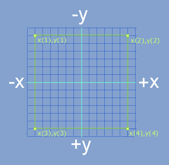 I=60
I=60As you can see, I've given an arbitrary value of -60 or +60 to each of the four points (or corners if you like). This means that each corner will be 120 pixels away from adjacent corners. By the way, the values in these 8 variables are never changed - even when we start moving and rotating. Instead, we store the rotation and movement in separate variables as offsets.
So then, we want to be able to display this square on the screen, and move it on the X and Y axis (horizontally across the screen and vertically up and down the screen) live while the program runs.
This is dead easy, and I'm sure you'd work out what to do, but here it is....
SIZE=40
START_LOOP
For N=1 To 4
X = X(N)+MOVEX
Y = Y(N)+MOVEY
Draw_Circle X+400, Y+300, SIZE
End_For
If Key=Cursor_Left ..... MOVEX = MOVEX-2 .... End If
If Key=Cursor_Right .... MOVEX = MOVEX+2 .... End If
If Key=Cursor_Up ....... MOVEY = MOVEY-2 .... End If
If Key=Cursor_Down ..... MOVEY = MOVEY+2 .... End If
|
Anyway, where were we. The KEY= lines refer to when you press the cursor keys on your PC's keyboard. This should move all four coordinates of the square in the appropriate direction.
SIZE is an arbitrary number to denote the size of the circle - nothing more. For now, I've given it an arbitrary value of 20 at the very beginning of the program.
Also, as you can see, the "For" & "End_For" commands make sure all 4 variables of the square in the array are affected together. Finally, the "400" and "300" numbers are arbitrary values to (hopefully) centralize the square on your 800*600 pixel screen. They can be other numbers if you like. Now run the program to see if it works how it should.
With me so far? Good.
---SCALE---
So we can move the square in all four directions. What else do we need to do? Well, for one thing, we need to scale it - to make it bigger or smaller. This is really easy to do :) Remember those two lines of SPLAT? Just replace the old two lines with these extended versions:
X = X(N) /SCALE +MOVEX |
Also change the circle line from:
Draw_Circle X+400, Y+300, SIZE
|
Draw_Circle X+400, Y+300, SIZE/SCALE
|
Now, give an arbitrary value of 1 to the SCALE variable, and put this at the very beginning of the program next to the SIZE=30 line (we don't want any divide by zero errors!). Finally, add a couple more key commands with the rest of the key commands, so that you can alter the scale live while the program is running. Something like:
If Key="[" .... SCALE = SCALE*1.02 .... End If |
---ROTATION---
So now we can move and scale the cube, what else do we need to do? This is the crunch - we need to rotate it about an arbitrary point or pivot. The code for this a bit more complex now, but the good news is that the 2D rotation code for doing this is effectively the same code we need for 3D rotation. In fact, one could say we're already in 3D territory, as we're going to be rotating this 2D square on the Z axis. As you might be able to guess, once we make the full move to 3D, we'll be using practically the same rotating routine for the X and Y axis, as we do here. OK, so this is what we use (deep breath):
XD = X(N)-PIVX |
Yes, I know; it's those evil SINE and COSINE commands ('Cos' and 'Sin'). What? You thought you'd able to escape those? ;)
Before you faint in terror though, let me give you a description of what this code actually /does/.
Imagine you have a point at coordinates X(N),Y(N). Picture a circular path coming from this point (yellow point in diagram), and circling around a separate pivot (blue point), eventually reaching back to the point (yellow point). Depending on the angle, what this code calculates is the X and Y offset required for this 'jump' to another position on this 'circle'. So, you input five variables (x+y original point, x+y pivot location, and angle.........., and the math outputs the desired two variables: the new x and y position (or rather, offsets) of the object point). Except you will not have to imagine any longer. A picture is worth a thousand words, so for a clear example of this, look at the diagram. You can skip trying to figure it out, but it's always nice to know what's going on.
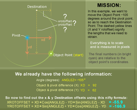
The code works globally for any point (good news for our square), and all it needs is for us to define the position of the pivot (If you leave out the pivot variables altogether, or define PIVX & PIVY as zero, then the square would rotate around the origin (x=0, y=0), or 'on the spot' in our square's case as it's centered on the origin), and for the angle of rotation (ANGLEZ - default again is zero), and then the code calculates the X & Y offset (XROTOFFSET & YROTOFFSET) automatically. By the way, XD and YD are just temporary variables - used mainly to simplify the look of the code.
I hope that makes some kind of sense. Don't worry if you don't know how Cosine and Sine combine to magically arrive at the appropriate X and Y offset. The main thing to know is that the code produces two offset numbers which just so happen to be needed in our ever-growing SPLAT routine (I told you SPLAT would come in handy). If you can remember it went from:
X = X(N) +MOVEX |
X = X(N) /SCALE +MOVEX |
X = [ X(N) + XROTOFFSET ] /SCALE +MOVEX |
Simply replace old SPLAT with this newest SPLAT.
Just before we move on, we need to add those all-important key command lines, so you can alter the angle and pivot location live while the program is running. The following two lines changes the angle:
If Key="1" .... ANGLEZ = ANGLEZ-1 .... End If |
If Key="f" .... PIVX = PIVX-2 .... End If |
Draw_Pixel (PIVX/SCALE)+MOVEX+400, (PIVY/SCALE)+MOVEY+300
|
SIZE=40
SCALE=1
I=60
X(1)=-I .... Y(1)=-I
X(2)=I ..... Y(2)=-I
X(3)=I ..... Y(3)=I
X(4)=-I .... Y(4)=I
START_LOOP
For N=1 To 4
XD = X(N)-PIVX

YD = Y(N)-PIVY


XROTOFFSET = XD*Cos{ANGLEZ} - YD*Sin{ANGLEZ} - XD

YROTOFFSET = XD*Sin{ANGLEZ} + YD*Cos{ANGLEZ} - YD
X = [ X(N) + XROTOFFSET ] /SCALE +MOVEX

Y = [ Y(N) + YROTOFFSET ] /SCALE +MOVEY
Draw_Circle X+400, Y+300, SIZE/SCALE
End_For
If Key="Cursor_Left" .... MOVEX = MOVEX-2 ...... End If
If Key="Cursor_Right" ... MOVEX = MOVEX+2 ...... End If
If Key="Cursor_Up" ...... MOVEY = MOVEY-2 ...... End If
If Key="Cursor_Down" .... MOVEY = MOVEY+2 ...... End If
If Key="[" ............ SCALE = SCALE*1.02 ... End If
If Key="]" ............ SCALE = SCALE/1.02 ... End If
If Key="f" .... PIVX = PIVX-2 .... End If
If Key="h" .... PIVX = PIVX+2 .... End If
If Key="t" .... PIVY = PIVY-2 .... End If
If Key="g" .... PIVY = PIVY+2 .... End If
If Key="1" .... ANGLEZ = ANGLEZ-1 ... End If
If Key="2" .... ANGLEZ = ANGLEZ+1 ... End If
END_LOOP
|
Isometric, 'true' 3D, and beyond
I=60 |
The next thing to do is change the line:
For N=1 To 4
|
For N=1 To 8
|
---ISOMETRIC---
 About the only difference between 2D and Isometric is the addition of more rotation code. In other words, we'll need to rotate on the X and Y axis, as well as the old Z axis. Thankfully, the new code is very similar to the code we've already got! Remember that previous Sine/Cosine nightmare? Yes, we return to that :) Previously, it was:
XD = X(N)-PIVX |
Replace the above 4 lines of old code (shown above) with this new code below. Look to see what's different. Note: XD, YD, ZD, and ZX, ZY, YX, YZ, XY, XZ are simply temporary variables. It's possible to use none of these variables, but it would've been at the expense of clarity (which is paramount at the moment - especially considering the apparent complexity of the routine). What's important to know is this whole routine will output just 3 important variables at the end (the X, Y & Z 'ROTOFFSETs').
XD = X(N)-PIVX |
In fact, the above code is just one of six possible configurations. I could have chosen five others, and the code would effectively execute the same thing.
Let's take another look at the second pair (YX= and YZ= lines):
YX = [XD+ZX]*Cos{ANGLEY} - ZD*Sin{ANGLEY} - [XD+ZX] |
Other changes from the old rotation code include the line: ZD = Z(N)-PIVZ ...and also the three lines:
XROTOFFSET = YX+ZX
YROTOFFSET = ZY+XY
ZROTOFFSET = XZ+YZ
These 3 statements simply add up all the 'rotational offsets', so that they can be used in the final SPLAT conversion routine.
Now just to add the usual keys, so that we can change the angles live while the program is running. We already have this:
If Key="1" .... ANGLEZ = ANGLEZ-1 .... End If |
If Key="3" .... ANGLEY = ANGLEY-1 .... End If |
That's it for isom! A second congratulations is in order. You should now be able to 'rotate' the cube in all 3 dimensions!
There's something not quite right though - something 'fake' about the way it's rotating, which moves us on to:
---'True' 3D---
This is the real thing. No more boring squares, no more fake cubes. Now we have Horizon and Parallax! Perspective! Camera location and angle! New variables! More opportunity for dividing by zero! (ummm... skip that last one ;)The rest of this tutorial will not add or change anything significantly to the existing code. Instead, we'll be adding little bits here and there, so that everything conforms to real 3D. I still like the isometric routine though, so there will be occasions where I won't replace code, but use an 'If' routine so that we can toggle between Isometric and Real 3D at will. In fact, we can do something about this now. Add this line at the start of the program:
MODE=0
|
If Key="Space_Bar" If MODE=0 MODE=1 SCALE=SCALE/CAMZ Else MODE=0 SCALE=SCALE*CAMZ End If Wait 2 End If |
The rest should be self explanatory. But hold your horses though - we haven't even defined what the CAMZ variable is yet, let alone why we need those SCALE=SCALE*/CAMZ lines. Suffice to say that the program will work without them, but unless we have them, the scale will go awry (massively too big or small) when we swap between the Isometric/true 3D modes while the program is running.
As for the CAMZ variable, well, this leads us nicely onto the Camera location...
---CAMERA---
We need a position for the 'Camera'. In other words, we need to define how far everything away is. For now, insert this code at the beginning of the program:
CAMX=0 ..... CAMY=0 ..... CAMZ=300
|
Now we pay a final visit to SPLAT (you knew that would come again sooner or later, didn't you).
Currently, SPLAT looks like this:
X = [ X(N) + XROTOFFSET ] /SCALE +MOVEX |
If MODE=0 X = [ X(N) + XROTOFFSET + CAMX ] /SCALE +MOVEX Y = [ Y(N) + YROTOFFSET + CAMY ] /SCALE +MOVEY Else Z = [ Z(N) + ZROTOFFSET + CAMZ ] X = [ X(N) + XROTOFFSET + CAMX ] /Z /SCALE +MOVEX Y = [ Y(N) + YROTOFFSET + CAMY ] /Z /SCALE +MOVEY End If |
Also, notice how the CAMera X and Y variables are /inside/ the brackets, while the normal movement variables (MOVEX and MOVEY) are /outside/ as usual. This is done because we're not just 'scrolling' a flat 'piece of paper', but instead moving the camera 'properly'. This way, we'll notice that the cube moves in /parallax/ (where the front of the cube seems to be moving more quickly horizontally/vertically across the screen, than the back). Naturally, we'll still be able to 'scroll' the scene in the old 'flat piece of paper' way (MOVEX & MOVEY) via the cursor keys, so we'll add different keys to move the camera around in a moment.
So let's take another look at this Z variable. Here again, are the three crucial lines of code:
Z = [ Z(N) + ZROTOFFSET + CAMZ ] |

- Sideline: What's so different between the CAMZ and SCALE variables? How will changing these differ in terms of how it looks? Well, one is moving the camera, and the other is 'moving' the scene. Here's another way of looking at it. There's two ways of 'zooming into' something. You can either /move forwards/ - which is what CAMZ does, or you can 'zoom in' by SCALING the scene (remember the flat piece of paper analogy). As you can see, there's a /big/ difference. Yet another way of looking at it is; If you just SCALE into the picture, you'll never be in front of it, now matter how big it gets. However, if you instead /move forward/ into the scene, then you'll get closer and closer (so it gets 'bigger' in that way), but at some point, you'll be out /in front/ of the object, and not be able to see it anymore. One last side effect: With CAMZ, you'll be able to see /parallax/. With ordinary scaling, it's just making everything look proportionally 'bigger' or 'smaller'.
So what next? To account for this new way of Camera 'moving', we'll need four more keys. I know - instead of using the cursor keys, we'll use the arrow keys of the keypad (which are 2, 4, 6, 8 ).
Add to the key press lines the following:
If Key="Keypad_4" ..... CAMX = CAMX-4 ...... End If |
The last thing we need to change is the circle line of code. Before, it looked like this:
Draw_Circle X+400, Y+300, SIZE/SCALE
|
If MODE=0 Draw_Circle X+400, Y+300, SIZE/SCALE Else Z = [ Z(N) + ZROTOFFSET + CAMZ ] Draw_Circle X+400, Y+300, SIZE /Z /SCALE End If |
Do you remember that line of code which displayed a pixel on the screen to represent the pivot? Well, here it is anyway:
Draw_Pixel (PIVX/SCALE)+MOVEX+400, (PIVY/SCALE)+MOVEY+300
|
PX = [ [PIVX+CAMX] / [PIVZ+CAMZ] ] /SCALE +MOVEX +400 |
>>>>>>>>>>> Initial start up variables:
SIZE=40
MODE=0
CAMX=0 ..... CAMY=0 ..... CAMZ=300 // Position of the camera.
MOVEX=0 .... MOVEY=0 .... SCALE=1 // Image fixed to 'paper' so you can move around and 'scale' in/out.
ANGLEX=0 .. ANGLEY=0 ... ANGLEZ=0 // Angle of rotation about the following pivots:
PIVX=0 ..... PIVY=0 ..... PIVZ=0 // Pivots x, y and z.
>>> Object coordinates (these 8 points form a cube):
I=60
X(1)=I .... Y(1)=I .... Z(1)=-I
X(2)=I .... Y(2)=I .... Z(2)=I
X(3)=I .... Y(3)=-I ... Z(3)=-I
X(4)=I .... Y(4)=-I ... Z(4)=I
X(5)=-I ... Y(5)=I .... Z(5)=-I
X(6)=-I ... Y(6)=I .... Z(6)=I
X(7)=-I ... Y(7)=-I ... Z(7)=-I
X(8)=-I ... Y(8)=-I ... Z(8)=I
<<<
>>>>>>>>>>>>>>>> Main loop code
START_LOOP
For N=1 To 8
>>> Rotation code
XD = X(N)-PIVX
YD = Y(N)-PIVY
ZD = Z(N)-PIVZ
ZX = XD*Cos{ANGLEZ} - YD*Sin{ANGLEZ} - XD
ZY = XD*Sin{ANGLEZ} + YD*Cos{ANGLEZ} - YD
YX = [XD+ZX]*Cos{ANGLEY} - ZD*Sin{ANGLEY} - [XD+ZX]
YZ = [XD+ZX]*Sin{ANGLEY} + ZD*Cos{ANGLEY} - ZD
XY = [YD+ZY]*Cos{ANGLEX} - [ZD+YZ]*Sin{ANGLEX} - [YD+ZY]
XZ = [YD+ZY]*Sin{ANGLEX} + [ZD+YZ]*Cos{ANGLEX} - [ZD+YZ]
XROTOFFSET = YX+ZX
YROTOFFSET = ZY+XY
ZROTOFFSET = XZ+YZ
<<<
>>> Yes, it's the *SPLAT* code (aka 2D to 3D conversion):
If MODE=0
X = [ X(N) + XROTOFFSET + CAMX ] /SCALE +MOVEX
Y = [ Y(N) + YROTOFFSET + CAMY ] /SCALE +MOVEY
Else
Z = [ Z(N) + ZROTOFFSET + CAMZ ]
X = [ X(N) + XROTOFFSET + CAMX ] /Z /SCALE +MOVEX
Y = [ Y(N) + YROTOFFSET + CAMY ] /Z /SCALE +MOVEY
End If
<<<
>>>>>> Drawing code
If MODE=0
Draw_Circle X+400, Y+300, SIZE/SCALE
Else
Z = [ Z(N) + ZROTOFFSET + CAMZ ]
Draw_Circle X+400, Y+300, SIZE /Z /SCALE
>>> Display of the pivot point code (optional)
PX = [ [PIVX+CAMX] / [PIVZ+CAMZ] ] /SCALE +MOVEX +400
PY = [ [PIVY+CAMY] / [PIVZ+CAMZ] ] /SCALE +MOVEY +300
Draw_Pixel PX, PY
End If
<<<
<<<<<<<
End_For
>>> Keys
If Key="Cursor_Left" .... MOVEX = MOVEX-2 ...... End If
If Key="Cursor_Right" ... MOVEX = MOVEX+2 ...... End If
If Key="Cursor_Up" ...... MOVEY = MOVEY-2 ...... End If
If Key="Cursor_Down" .... MOVEY = MOVEY+2 ...... End If
If Key="[" .............. SCALE = SCALE*1.02 ... End If
If Key="]" .............. SCALE = SCALE/1.02 ... End If
If Key="1" .... ANGLEZ = ANGLEZ-1 .... End If

If Key="2" .... ANGLEZ = ANGLEZ+1 .... End If
If Key="3" .... ANGLEY = ANGLEY-1 .... End If
If Key="4" .... ANGLEY = ANGLEY+1 .... End If
If Key="5" .... ANGLEX = ANGLEX-1 .... End If
If Key="6" .... ANGLEX = ANGLEX+1 .... End If
If Key="f" .... PIVX = PIVX-2 .... End If

If Key="h" .... PIVX = PIVX+2 .... End If

If Key="t" .... PIVY = PIVY-2 .... End If

If Key="g" .... PIVY = PIVY+2 .... End If
If Key="a" .... PIVZ = PIVZ-2 .... End If
If Key="s" .... PIVZ = PIVZ+2 .... End If
If Key="Keypad_4" .... CAMX = CAMX-4 .... End If
If Key="Keypad_6" .... CAMX = CAMX+4 .... End If
If Key="Keypad_8" .... CAMY = CAMY-4 .... End If
If Key="Keypad_2" .... CAMY = CAMY+4 .... End If
If Key="Keypad_-" .... CAMZ = CAMZ-4 .... End If
If Key="Keypad_+" .... CAMZ = CAMZ+4 .... End If
>>> Toggle True 3D and Isometric routine
If Key="Space_Bar"
 If MODE=0
  MODE=1
  SCALE=SCALE/CAMZ
 Else
  MODE=0
  SCALE=SCALE*CAMZ
 End If
 Wait 2
End If
<<<
END_LOOP
---------------------End |
ANGLEX=ANGLEX+5 |
Well, it goes without saying that you can feed just about any shape into the program. There's nothing to stop you from rotating and moving dodecahedrons or entire game-scapes if you so desire (and if your pc is fast enough ;)
As an exercise for the reader, try to build up a 1,000 point 'cube' (10*10*10) points by adding a relatively small amount of code to the beginning. The effects of 3D look spectacular when there are so many points to rotate and move through! /Especially/ if your PC is fast enough to display everything in 50 FPS (frames per second) realtime.
At the moment, the program uses simple circles, but it shouldn't take too much effort to replace these circles, and have lines joining up to make a wireframe cube. Apart from that, we could explore using matrices, solid shading, texture mapping, even gouraud shading, light sources and 4D+. We'll leave all that for another time though...
Well, I hope I've made it an interesting and informative article! Please let me know if this article has helped you understand 3D a bit better. Also, if there's something I should edit to make clearer, then I'd be interested to know how. [Back to top]
or email here
- Scaling, rotating and translating coords
in 2 and 3 dimensions using matrices - - - An overview of how you would use matrices to represent rotation, translation, and scaling functions.
- Tube Complex - - - The main gallery's Tube Complex (ray-traced pictures).
- Stereoscopic 3D gallery - - - Computer generated 3-dimensional graphics. Many require '3D glasses', but you can see some of them by crossing your eyes.
- Light and Colour Trivia - - - Contains a section on 3D. Also find out why yellow and blue doesn't make green..
Back to top
Skytopia home > Project index > Rotating cube tutorial

All text on this page is copyright D. White 2002 onwards.
Please ask for permission should you wish to use the text material on these pages.
